Showing posts with label arduino. Show all posts

Thursday, January 2, 2014

Getting and sending analog data over bluetooth with Arduino Pro at 8 MHz

I am thinking of using the ATmega328 running at 8MHz for the microcontroller on my wireless module.  To gather neural data, I am contemplating using an Intan chip, possibly the RHD2216 which can communicate with the ATmega328 using SPI:


I will not be able to send all 16 channels (at 16 bits) at a reasonable sample rate unless I do some compression, however, I think I can send 8 channels reasonably.  As proof of principle, I set up an Arduino Pro (ATmega328, 8MHz) getting data via SPI from an MCP3208 and sending via bluetooth.

Aside: I could compress sent data by sending only changes in ADC values, which are likely far smaller than the full 16 bits.  If I could get away with sending only 8 bits, then I could send all 16 channels at a reasonable sampling rate.

In any case, I found that on the 8MHz chip, just performing SPI communication was a little slow when using digitalWrite/digitalRead.  I started out using code from http://playground.arduino.cc/Code/MCP3208, but it ran too slow.  I had make things faster.  Here is what I had to do:

  1. Use port manipulation where possible (this make the code less portable)
  2. Remove any loops (e.g. for loops for sending bits)
  3. Use digitalWriteFast and digitalReadFast available at: https://code.google.com/p/digitalwritefast/
  4. Cycle the SPI clock with a minimal delay supported by MCP3208 - in case of 8 MHz, a single asm("nop\n") call is enough
So the result is that I can read and send 8 16 bit values from the ADC at 500 Hz.  The rate-limiting step here is reading the data, but the only way to go faster is to run faster chips.  The Intan chip is capable of running at 24MHz and has 16, 16Bit differential inputs plus amplifiers.  This may or may not be overkill for our application.

Monday, December 23, 2013

Good data rate from Arduino over Bluetooth Serial

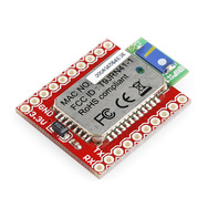
I am designing a better wireless data transmitter.  To do this, I have decided to switch from XBee to a bluetooth module.  I purchased the following:


Bluetooth Module Breakout - Roving Networks (RN-41)
https://www.sparkfun.com/products/12579

The Roving Networks module is easy to use once you figure out how to pair it with your PC.  Here is how I did it:

2.  Pair the module with your PC using the default pairing code on the Roving module "1234"
3.  Find out the mapped serial port.  On my computer this produced two ports, only one of which worked for connecting to the module.
4.  Set the appropriate baud rate.  The module comes pre-configured for 115200 baud, however, I found it helpful to set the baud to 9600 to get started by putting pin GPIO7 to VDD.
5.  Program the module (including name) using PuTTY as follows:
     a.  Ready the PuTTY connection 
     b.  Power on the module
     c.  Connect via PuTTY within the first minute and enter programming mode by sending $$$ to the module
     d.  Program the module using instructions in:  https://www.sparkfun.com/datasheets/Wireless/Bluetooth/rn-bluetooth-um.pdf

I hooked it up to my Arduino Mega powered from the 3.3V output and with the transmit pin of Serial1 connected to the receive pin of the RN-41 through a voltage divider: 

TX1 (pin 18) via 10K/20K voltage divider to TX pin on the RN-41

I also added some LEDs for status output on pins PIO5 and PIO2 which together help me understand the status of the module (PIO5 blinks 1Hz when waiting for connection and 10Hz 10Hz when in command mode and PIO2 is on solid when connection is made)

Here is what it looks like:


I then wrote a little Arduino sketch for testing how fast I could get data to the PC via bluetooth.  I am interested in sending analog values to the module, so I simulated that by reading analog channels on the Arduino (for now).  I intend to send that data as unsigned integers with 16 bit precision so what I am doing is sending over 16 ASCII characters ("ABCDEFGHIJKLMNO_").

Here is my code:

unsigned int val;
unsigned int fakeVal[8];
char *p_val;
int count;
int reportCount;
int nChans;
unsigned long t0;
char str[17] = "ABCDEFGHIJKLMNO_";

void setup() {
  Serial.begin(115200);
  Serial1.begin(115200);
  count = 0;
  reportCount = 2000;
  nChans = 8;
  
  p_val = &str[0];
  //p_val = (char*)&val;
  t0 = millis();
}

void loop() {

  int i;
  for (i=0;i<nChans;i++)
  {
    val = analogRead(i); // 100 microseconds
    Serial1.write(p_val[i*2]);
    Serial1.write(p_val[i*2+1]);
    delayMicroseconds(97);
  }
  
  if (++count==reportCount) {
    Serial.print("Simulating ");
    Serial.print(nChans);
    Serial.println(" 16 bit channels");
    Serial.print("Data rate: ");
    Serial.print(1000.0*((double)reportCount)/((double)(millis()-t0)));
    Serial.println(" values per channel per sec");
    count = 0; 
    t0 = millis();
  }
}

I am using PuTTY to monitor the arriving data and things look pretty good sending 16 bytes at 500 Hz.  


The theoretical limit of an 115200 bps connection is 115200/16/8 = 900 Hz, however, I find that the connection is unstable (i.e. module spontaneously disconnects) at anything much over 600 Hz.  This may be a PuTTY problem so we'll see if I can get up to the max.

As for power requirements.  Bluetooth pulls about 50 mA of current in default power mode.
Here are my power readings:

Setting  Output (dBM)  Current Draw (mA)
                         Approximate via FLUKE Multimeter
SY,0004       4              50
SY,0001       0              43
SY,FFFC      -4              40
SY,FFF8      -8              40
SY,FFF4      -12             50-80 (choppy connection?)

This range of current draw is similar to what is described for the XBee so this thing may still play nice with the battery though I do not know if the battery will survive this thing PLUS an arduino... only one way to know :)

Sunday, February 24, 2013

Arduino I2C DAC Array Using MCP4725

The XBee in line passing mode would output signals via PWM.  However, this method is not very good because of the low PWM frequency of the XBee and the need to filter signals introducing additional phase delays on top of transmission times.

To remove this problem, I use an Arduino to receive signals from XBee and send appropriate values to an array of MCP4725 DAC chips.

The MCP4725 chips come with a set address on I2C with just one address bit selectable by the user.  To implement the DAC array, connected the selectable address bits of the DACs on the I2C to digital outputs of the Arduino.  To select one DAC for writing, the Arduino sets its address bit high.  The Arduino is programmed to write to that specific address.

Here is the datasheet for the MCP4725:
http://www.sparkfun.com/datasheets/BreakoutBoards/MCP4725.pdf

All schematic etc can be found here: https://docs.google.com/folder/d/0Byu6zHhzDPqVQlEtMFBaeHRZUlE/edit?usp=sharing

Here is my breakout board for an array of four MCP4725s and a picture of the array on top of the XBee shield from sparkfun:
The green colored board is the DAC breakout.  Blue is the XBee and red is the SparkFun XBee Shield.

The PCB Layout.

The circuit schematic.
The Arduino code is as follows:


#include <Wire.h>

#define BUFFER_LEN 64

// constants
#define START_DELIMITER 0x7E
#define API_ID          0x83

#define PACKET_LEN      0x10
#define N_SAMPLES       0x01

#define MCP4725_ID      0b01100000  

int DAC_BUS_PINS[] = {9,11,12,13};
int N_DAC = 4;

int i, j;

byte buffer[BUFFER_LEN];
byte L12[2];
byte dac_bits[2];

// the setup routine runs once when you press reset:
void setup() {
  // initialize serial communication at 115200 bits per second:
  Serial.begin(115200);
  Wire.begin();
  
  
  for (i=0;i<N_DAC;i++)
  {
    pinMode(DAC_BUS_PINS[i],OUTPUT);
    digitalWrite(DAC_BUS_PINS[i],LOW);
  }
  
  dac_bits[0] = 0;
  dac_bits[1] = 0;
}

// the loop routine runs over and over again forever:
void loop() {
  
  int len;
  unsigned char firstByte;
    
  int value, X, Y, Z;
  word adc_val;

  if (Serial.available()) {
  
    firstByte = Serial.read();

    if (firstByte==START_DELIMITER) // start of a packet
    {
      Serial.readBytes((char*)L12,2);
      len = word(L12[0],L12[1]);

      if (len==PACKET_LEN) { // check for API packet of right length
        
        Serial.readBytes((char*)buffer,len);  
       
        //      [ sniff |   X   |   Y   |   Z   ]
        //buffer[  8, 9, 10, 11,  12,13,  14,15 ]
       
        // DAC Communication
        for (j=0;j<N_DAC;j++)
        {
          // adc value
          value=word(buffer[(j*2)+8],buffer[(j*2)+9]);
          //value=word(buffer[8],buffer[9]);
          adc_val = value*4;
   
          digitalWrite(DAC_BUS_PINS[j],HIGH); // address a DAC chip [0b1100011]
          Wire.beginTransmission(99); //99
          Wire.write(0b01000000); // write dac register command [c2 c1 c0 x x pd1 pd0 x]  for write dac c2 = 0, c1 = 1, c0 = 0
          for (i=0;i<8;i++) bitWrite(dac_bits[0],i,bitRead(adc_val,i+4)); // shift bits around for making i2c compatible
          for (i=0;i<4;i++) bitWrite(dac_bits[1],i+4,bitRead(adc_val,i));
          Wire.write(dac_bits[0]);
          Wire.write(dac_bits[1]);
          Wire.endTransmission();
          digitalWrite(DAC_BUS_PINS[j],LOW); // null DAC address to [0b1100010]
        } 
        // END DAC Communication  
      }          
    }
  }
  
}

Wireless Movement & Sniffing Monitor

Using an XBee, Arduino, and some sensors (accelerometer, pressure sensor), we put together this wireless movement/sniffing monitor.  The device is powered by a 3.7V rechargeable Lithium Ion coin cell.  The small (4cm x 4cm) board connects via a magnet so it is easy to put on and off.  Optional LEDs can be used for tracking.  I am using the native ADCs on the XBee for passing signals.

In the next post I will put the Arduino code and circuit for receiving the signal from the sensor board.

The accelerometer is Analog Devices ADXL335: http://www.analog.com/static/imported-files/data_sheets/ADXL335.pdf
The amplifier for pressure sensor is Analog Devices AD627: http://www.analog.com/static/imported-files/data_sheets/AD627.pdf
The pressure sensor is Honeywell 24PCAFA6G: http://sccatalog.honeywell.com/pdbdownload/images/24pc.series.chart.5.pdf

The magnetic clip is made so as to connect the pressure sensor to a cannula on the other side of the connector and to prevent arbitrary rotation.

Here is a video of the magnetic clip:


Here are pictures of the device:
Front of board with XBee removed.  Pressure sensor and magnetic attachment on bottom.

Back of board has battery clip.
Front of board with XBee.


Magnetic attachment around pressure sensor and mating piece (right).

Here is the link to the project files and some additional information below:
https://docs.google.com/folder/d/0Byu6zHhzDPqVQlEtMFBaeHRZUlE/edit?usp=sharing
The PCB Layout that I used.

The circuit schematic.


Monday, January 21, 2013

Sending wireless signals with XBee & Arduino

We recently needed to make a system by which we can send sensor data from a freely moving animal wirelessly.  One simple way to do this is by using XBee modules from Digi.  These modules are fairly small (about the size of a quarter) and are incredibly easy to use in a new project.  We received a pair from SparkFun to play with.

Here is the information on XBee:
Product: https://www.sparkfun.com/products/11215 ($22.95)
Datasheet: http://www.sparkfun.com/datasheets/Wireless/Zigbee/XBee-Datasheet.pdf

We also got accessories:
XBee Shield: https://www.sparkfun.com/products/10854 ($24.95)
XBee Explorer Dongle: https://www.sparkfun.com/products/9819 ($24.95)

Also, I downloaded the X-CTU software from Digi: http://ftp1.digi.com/support/documentation/90001003_A.pdf

My plan was to use the on-board AD on the XBee to sample an analog signal (max sampling rate 1 kHz) and to send it to a receiving XBee and then to Arduino (an old Demilanove) for processing and output using an I2C DAC.

For DAC, I got MCP4725 breakout from Sparkfun:
https://www.sparkfun.com/products/8736 ($4.95)

Overall, this project cost: $100.75 not counting the Arduino, which I already had on hand.

First, I configured the two XBee modules to talk to each other using X-CTU and XBee Explorer Dongle.

Transmit Module Settings: 
DL = 1234  //Destination Address Low
MY = 4321 //Source Address
BD = 7 //Interface Data Rate: 115200
D0 = 2 //Digital input 0 is ADC
IT = 4 //Samples before transmitting = 4
IR = 1 //Sampling rate = 1 (1kHz)

Receive Module Settings:
DL = 4321 //Destination Address Low
MY = 1234 //Source Address
BD = 7 //Interface Data Rate: 115200
AP = 1 // API Enable
IA = 4321 // I/O Input Address

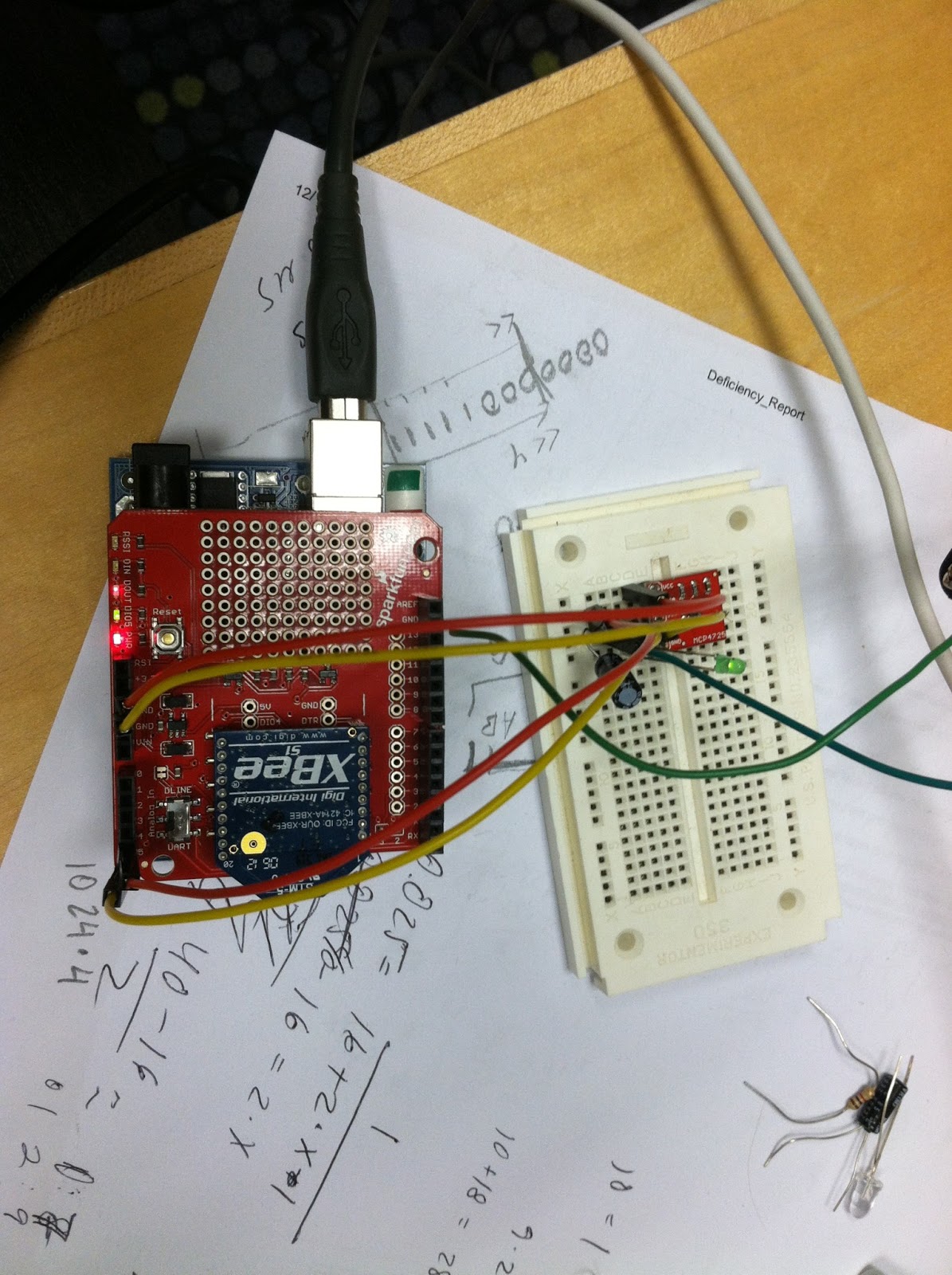
Next, I put the Transmit module on the dongle on a breadboard hooked up to a signal source (in this case a pressure sensor).  I put the Receive module on the Arduino Shield and also hooked up the DAC on a separate breadboard.  The setup looks like so:

Transmit Module with pressure sensor input.
Receive Module with Arduino and DAC.

To communicate with I2C, I am using the Wire library for Arduino.  To read packets from the XBee, I wrote a really simple little script:


#include <Wire.h>

#define BUFFER_LEN 64

// constants
#define START_DELIMITER 0x7E
#define API_ID          0x83

#define PACKET_LEN      0xA //0x10
#define N_SAMPLES       0x01

#define MCP4725_ID      0b01100000  

int i;

byte buffer[BUFFER_LEN];
byte L12[2];
byte dac_bits[2];

// the setup routine runs once when you press reset:
void setup() {
  // initialize serial communication at 9600 bits per second:
  Serial.begin(115200);
  Wire.begin();
  
  for (i=0;i<10;i++)
    pinMode(i+2,OUTPUT);
  
  dac_bits[0] = 0;
  dac_bits[1] = 0;
}

// the loop routine runs over and over again forever:
void loop() {
  
  int len;
  unsigned char firstByte;
    
  int value;
  word adc_val;

  if (Serial.available()) {
  
    firstByte = Serial.read();

    if (firstByte==START_DELIMITER) // start of a packet
    {
      Serial.readBytes((char*)L12,2);
      len = word(L12[0],L12[1]);

      if (len==PACKET_LEN) { // check for API packet of right length
        
        Serial.readBytes((char*)buffer,len);  
        
        // add 4 samples together
        value = 0;
        for (i=0;i<N_SAMPLES;i++)
          value+=word(buffer[(i*2)+8],buffer[(i*2)+9]);

        adc_val = value * (4 / N_SAMPLES);
        
        // DAC Communication
        Wire.beginTransmission(96);
        Wire.write(0b01000000); // write dac register command [c2 c1 c0 x x pd1 pd0 x]  for write dac c2 = 0, c1 = 1, c0 = 0
        for (i=0;i<8;i++) bitWrite(dac_bits[0],i,bitRead(adc_val,i+4)); // shift bits around for making i2c compatible
        for (i=0;i<4;i++) bitWrite(dac_bits[1],i+4,bitRead(adc_val,i));
        Wire.write(dac_bits[0]);
        Wire.write(dac_bits[1]);
        Wire.endTransmission();
        // END DAC Communication  
      }          
    }
  }
  
}
The Arduino is plenty fast to handle all the data from the XBee.  However, I was not pleased to see that the real-world transmission rate for the XBee capped out at 1 packet every 5 msec or 200 Hz.  This means that if you are sampling and transmitting as fast as possible, you take only one sample every 5 msec in the end.  This leads to a minimum 5msec lag in the system.  If you acquire more samples as in my case (4).  You get a 10 msec lag and a sampling rate of 100 Hz.

Averaging 4 samples let's me effectively improve the ADC resolution to 12 bits fro the 10 bit native on the XBee.

It works overall.  Here is a 10 Hz sine curve passed at 4 samples per packet compared to the original:


If I do not do any averaging and just send one sample at maximum settings data looks like:


Feeding this signal into a proper ADC like one from National Instruments sampling at 1 kHz, it should be fine to resolve and time-stamp individual samples.

NOTE: Reading the data using Arduino and then passing it to DAC is better than filtering the native PWM of the XBee.  This is because filters that can cut out the PWM frequency of the XBee (which runs at 15.6 kHz) will yield significant amount of distortion for signals near the cutoff.  For example, Digi suggests using the following RC combination to filter: 850 Ohm, 1 uF.  Fc = 187 Hz.  However, using this filter with signals at 50 Hz, you will get a lot of phase distortion.  This does not happen with a DAC.  Further, the XBee actually receives the data as digital values.  It makes no sense to convert those to PWM unless you absolutely can't afford to have the Arduino/DAC.

In conclusion, however, for faster signals, we will need a different radio.  Perhaps a bluetooth one.

Sunday, June 17, 2012

Fake Neuron in Arduino

I am getting ready to go ahead with electrophysiology experiments recording from the olfactory bulb.  To test my acquisition equipment and software, I created a little Arduino program that simulates a simple neuron with firing rate driven by "sniffing".  The neuron generates Poisson action potentials with the rate parameter governed by a sinusoid (sniffing).

The shield has an LED that indicates the sniffing and a speaker that indicates the spiking.  Here is the shield and program in action (turn volume to max to hear the neuron):


And here is the sketch:


/*
  Fake Neuron
  Yevgeniy Sirotin, 6/16/12
 */


#include <math.h>


unsigned long t0;
unsigned long t;
unsigned long ti;


int ts;
float r;


void setup() {
    pinMode(9, OUTPUT); 
    pinMode(7, OUTPUT);
    t0 = millis();
    
    TCCR1B = 0x01;
    
    ti = 0;
    ts = 0;
}


void loop() {
    t = millis();
    
    r = 0.5 * (1.0 + sin( (float) ((t-t0) % 2000) * 2.0 * 3.14 * 1.0 / 1000));
    analogWrite(9, (int) (255.0 * r ));
       
    if (t>=ti)
    { 
      digitalWrite(7,HIGH);
      delay(1);
      digitalWrite(7,LOW);
      
      if (r<0.1) r = 0.1;
      ti = t + (unsigned long) (-1000.0 / (100 * r) * log(random(10000) / 10000.0 ));
      
   }      
}

Saturday, May 26, 2012

8Kb is not a lot

...but it just has to do.

The Arduino with the Atmega chip has only 8Kb bytes of RAM.  In writing my Arduino-MATLAB interface I came up hard against that limit.  My interface works by allowing a user to upload a small program to the Arduino that uses a locally defined function library.  I realized something was funny when programs will too many instructions failed.  This was because when program upload size exceeded a certain value, the Arduino would crash because it could no longer allocate memory for the incoming data.  By being more careful with memory, I was able to extend the amount I could send.

Also I found some nice ways to check the amount of memory available to malloc.  In the following code, x is there just to test that this function is working properly (i.e. detecting a prior malloc usage):


void funcFreeMem(IN_FREE_MEM_FUNC *in,OUT_FREE_MEM_FUNC *out)
{
  int sz = 0; 
  
  byte* x = (byte*) malloc(in->in * sizeof(byte));
  
  byte *buf;
  while ( (buf = (byte*) malloc (sz * sizeof(byte))) != NULL ) {
    sz++; // if allocation was successful, then up the count for the next try
    free(buf); // free memory after allocating it
  }
  
  free(buf);
  free(x);
  out->mem = sz;
}

Saturday, May 12, 2012

Arduino PWM Filter

To get nice analog signals from the Arduino PWM pins it is necessary to filter the output.  Arduino PWM is somewhat slow, frequency of 15.6 kHz at 10 bit timer resolution (see this post on configuring the timer).  Luckily this is fine if you do not care about signals faster than 1 kHz.  Indeed I find that the Arduino can't really generate sine curves faster than about 0.1 kHz.  So it makes sense to just filter signals to maximally attenuate the PWM noise while retaining signals slower than 0.1 kHz.

This requires us to design a low-pass filter.  Now, doing some research, it is easy to find recipes for all kinds of analog filter designs, however, a simple RC filter does just fine for our needs.  I found a nice tutorial online explaining how the RC filter works.  The main formula needed is that the time constant of the RC circuit is related to the cutoff frequency as:  Tau = RC = 1/(2*pi*f)

So we have PWM at 15.6 kHz and we want to pass signals of 1 kHz, which means we should put our cutoff frequency at just a little above 1 kHz, say f = 2 kHz.  We get Tau = 1/(2*pi*2 kHz) = 8e-5 sec.  For a resistor of 1 kOhm, that gives a capacitor of 0.08 uF.  However, the attenuation of an RC filter is rather poor with only a -20 dB decrease per decade.  This means that for this cutoff we will be attenuating the PWM signal by only ~20 dB or ~10 times.  So a 5 V pwm will still show up as a ~500 mV signal on our output.  

To improve our results, I sometimes use a combination of a 1 kOhm resistor and a 1 uF capacitor with Tau = 1 msec.  This gives a cutoff frequency of 159 Hz, acceptable given that the Arduino has trouble with signals faster than 100 Hz and attenuates the PWM frequency significantly more (~-40dB) or only ~50 mV left of our 5 V PWM signal.

Open-Source Arduino-Based Olfactometer Shields

We just put together a set of shields to allow Arduino-based olfactometer control.  I am including the linked schematics here.  To make these shields, we are using a program called ExpressPCB, which is linked to a printing service.  I will not go through the details of what component goes where on the PCB, but I assume anyone with some electronics know-how should be able to figure them out.

ArduinoShieldBasic.pcb - Template we use for designing shields for Arduino Mega

rs232shield2.pcb - A module we use to communicate with Alicat MFCs

This module converts from Arduino's TTL serial to RS232 serial.  It also has a pwm signal filter and unity gain to allow analog output from two channels on the Arduino for control using an analog voltage.

valvedriver3.pcb - The valve-driver module for controlling odor valves

The module has optocouplers to switch solenoids on or off and status LEDs to view valve state.

valvedriverSMT.pcb - Another valve driver module with ribbon cable breakout (below)
ValveBreakout.pcb - the breakout with indicator LEDs


Valve - breakout


Valve - driver

Monday, March 19, 2012

MFC Control Complete

Today I finished implementing control over my mass flow controllers from Alicat.  I now have the capacity to drive two MFCs via analog voltage or serial from our custom Arduino shield.  Everything works directly from MATLAB.

This is our Arduino-based olfactometer control module connected to two Alicat MFCs.
The output works at high frequencies with the MFCs being able to follow up to 3 Hz well.  I doubt that this performance will be maintained with long downstream tubing, but I hope to be able to do at least 1 Hz at output.

I had to work out a kink to get switching between serial and analog control to work.  The Alicat documentation says that A$$W20=16384 should enable analog set point. However, I found that this does not work.  Reading register 20 after setting analog set point from the front panel, however, showed that the correct value is actually 17408.

The Arduino will start by default in analog control mode. To switch modes:

[mode] = {0: SERIAL_OUT, 1: ANALOG_OUT}
olf.funcALIMode([mode]);

I tested the whole setup using my handy dandy flowmeter and things work very well so far.  Here is the code I used for my current test setup:


olf = OlfactometerDriver_SerialInterface('COM10'); pause(12);


% proportional control var
olf.funcALIMessage('A$$W21=500')
% differential control var
olf.funcALIMessage('A$$W22=10')


olf.funcALISin(1,1,0.5);
olf.funcALISin(0,1,0.5);


Next step: connect the MFCs to the olfactometer, determine the right parameters for sinusoids, and verify output via PID.


Saturday, March 17, 2012

Arduino Timer Configuration for 10bit Analog Output

Two things matter for PWM analog output:

1. PWM Frequency
2. PWM Resolution

The Atmega1280 comes with a couple of timers that control PWM on specific pins.  These timers are, by default, set for 8bit operation and a prescale value of 64.  That means that the timer resets every 256 ticks and each tick is 64 clock cycles.  The Atmega1280 runs at 16 MHz so, by default the timer frequency is 1/64th of that, or 250 KHz and the timer cycle is 1/256th of that, or ~977 Hz.

This is fine so long as you want fairly crude signals, but I wanted signals good to the millisecond and better bit depth.

The manual for the Atmega1280 is fairly clear:  http://www.atmel.com/Images/doc2549.pdf

PWM frequency can be increased by setting the prescale value to 1 (i.e. the 16 MHz clock).  PWM resolution can be increased by increasing the number of timer ticks in the cycle from 256 (8 bit) to 1024 (10 bit).  This produces a PWM of 16 MHz / 1 / 1024 = 15.6 KHz.  Much better!

Since I am interested in signals << 1KHz, I can simply run the PWM output through an RC circuit with a time constant of 1 msec  (e.g. 1 uF capacitor and 1K resistor).  This produces a reasonable sine function for frequencies up to ~50 Hz.

This code, which runs in setup(), applies the aforementioned settings for Timer 1, which controls pins 11 to 13 on the Arduino Mega.  To understand it, one has to dig through the manual for the descriptions of registers TCCR1A and TCCR1B.


  // set Timer1 (pins 13 and 12 and 11)
  TCCR1B = 0x09;  // set Control Register to no prescaling 
                  // WGM02 = 1


  TCCR1A = 0x03;  // set WGM01 and WGM00 to 1 (10 bit resolution)

Friday, March 16, 2012

Arduino as Analog Function Generator

I realized that outputting functions over the serial port is a little too much overhead.  However, my MFCs can be controlled by analog signals on input pin 4 in the miniDIN.  So I decided to see if the Arduino can output reasonable signals by PWM.

I generated a sin using PWM and filtered the signal using a simple RC circuit (tau = 1 msec).  It took a little fiddling with the Control Register of the appropriate timer (I had to remove prescaling) to get good output PWM frequency, but it looks pretty good.

This is my test code:


unsigned long t0;


void setup() {
    pinMode(9, OUTPUT); 
    t0 = millis();
    
    TCCR1B = 0x01;
}


void loop() {
    analogWrite(9, (int) (255.0 * 0.5 *(1.0 + sin( (float) ((millis()-t0) % 1000) * 2.0 * 3.14 * 5.0 / 1000))));    
}

UPDATE: click here for explanation of my choice of RC filter

Along the way, I found this useful blog with info about the Arduino:
http://softsolder.com
http://softsolder.com/2010/09/05/arduino-mega-1280-pwm-to-timer-assignment/
http://softsolder.com/2009/02/21/changing-the-arduino-pwm-frequency/ 

Thursday, March 15, 2012

Speedy MFC!

So it turns out there was a setting on the device that adjusts the speed with which the MFC operates.  Here I demo both the nice speed of the MFC and how it follows a 2 Hz sinusoid put out by my Arduino.

In order to do this, I had to change the "Proportional Control Variable" from the default value 100 to 500.  The documentation is not clear on what this variable is, but changing it sure does speed things up.  Here's how I did it all from MATLAB:

>> ret = olf.funcALIMessage('A $$W21=500'),

ret = 

    funcName: 'funcALIMessage'
         str: 'A   021 = 00500
                                                '


ret = olf.funcALISin(2,1,0.5),

ret = 

    funcName: 'funcALISin'
       state: 0


 And here's the flow output:


My Awesome Test Setup

Here's a picture of my setup.  On top of the Arduino is our custom valve driver shield.  Attached to the shield DB9 port is my hastily soldered inverter.  That connects to the Alicat MFC.  The Arduino is also connected to the PC by its USB port.

PC (MATLAB) --> Arduino --> MFC


Below is what interacting with the MFC looks like from MATLAB.


Wednesday, March 14, 2012

Just resolved sending also and I got my first serial port comm between Arduino and the MFC.  In the end, I simply inverted both the transmit and receive signals.

In the light of the morning

In the light of the morning, answers come:
http://www.sparkfun.com/tutorials/215

It looks like the MFC is using an RS232 standard but the Arduino is using TTL serial standard.  These two protocols differ in two main ways:

1. TTL is high for 1 and low for 0, whereas RS232 is the opposite
2. The voltages on TTL and RS232 can be wildly different

However, I happen to know that the voltages one the two devices are ok, so for me its just a matter of inverting the signal.  I can in principle just get a signal inverter, however, I will also order a RS232 to Serial converter:

RS232 Shifter SMD
http://www.sparkfun.com/products/449

Update, I added a simple voltage inverter circuit in front of the receive on the Arduino and MAGIC, it now reads the signals from the MFC just fine!  Now all that is left is sending...

Tuesday, March 13, 2012

RS 232 Voltages

I managed to get some serial input from the MFC to the Arduino, however, the input was garbled!  One cause of this could be that the RS 232 voltage levels sent by the Alicat MFCs are inappropriate for the Arduino to handle directly.  I will call tech support tomorrow to determine their exact specs to see if all could be fixed with a simple resistor or if I will need some more serious circuitry.

However, I measured the output signal on my oscilloscope and I see that it indeed is 0-5V, which should be fine as far as the Arduino is concerned.  Strange behavior.